Introduction
In the past few releases, Network Director has greatly eased the complexity in provisioning/managing different topologies such as “Virtual Chassis Fabric”, “Layer 3 Fabric” etc. Network Director 3.0 supports provisioning/managing of Junos Fusion systems. The objective of this article is to illustrate how Network Director simplifies the deployment of Junos Fusion by automating several aspects that are required in setting up Junos Fusion with hybrid (standalone and cluster) satellites.
Network Builder
It would be easier if all supported topologies are integrated as part of a common workflow. “Network Builder” is a common launch point that helps the user set up different supported topologies that are applicable to both campus and data center environments.
“Build” mode in Network Director 3.0 has a new task group called “Network Builder”. The “Network Builder” task group has the task to "Manage Fusion Config. Templates" and "Manage Fusion Fabrics".
Templates
In large campus and data center environments, several instances of similar topology (Virtual Chassis Fabric/Junos Fusion/Layer 3 Fabric etc.) are possible. Not only is it cumbersome to create an instance one at a time but also error prone and difficult to manage. The common settings that are applicable to several instances can be abstracted to a template and can be applied to bring up one or many instances. The template will not have any configuration that is instance specific. The user will have to provide instance-specific configuration attributes at the time of applying/assigning a template. The user will be able to create as many templates as required for different topologies. After the template is created, the template would appear in the template-landing page. The user will be able to execute template-related operations (such as create a template, clone a template, view and delete the template) from the template-landing page. The user will not be able to edit a template once it is created.

Figure 1. Manage Fusion Configuration Templates Landing Page
Junos Fusion Single Home with Hybrid Satellites Template Creation
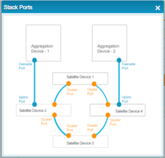
Figure 2. Cluster Ports (marked in Orange)
The user will be able to initiate the workflow to “Create Template” from the “Template Landing Page”. The workflow will prompt for user input based on the topology (single-home or dual-home) selected in the “Create Template” wizard. In the wizard, to begin with, the user builds the chassis of the aggregation device by mapping the line card to the respective slot as found in the physical device. The user provides cascade ports (ports for connecting satellite devices) to the aggregation device. If the topology has a cluster of satellite devices (that is, a collection of satellite devices that are connected as a ring with only a few devices directly connected to the aggregation device), the user also provides the ports on the satellite device models that will be connected to form a ring topology. The ports that are connecting the ring of satellite devices are termed as "cluster" ports. Finally, the user selects the default SNOS image that will be loaded on the satellite device model when connected to the aggregation device. The template once created will appear in the “Template Landing Page” and can be applied to bring up one or many instances of Junos Fusion.
Network Director 3.0 supports EX43XX models as satellite devices and it is required that ports on PIC 1 and PIC 2 be used as cluster ports. Based on the selected satellite device model, Network Director assists the user in making the cluster port selection by filtering only the supported ports that can be selected as cluster ports. The ports highlighted in orange in Figure 2 indicates cluster ports.
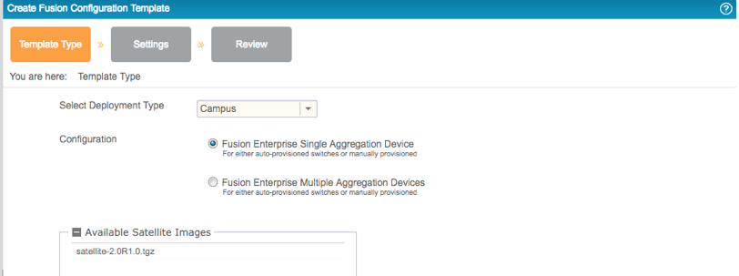
Figure 3. Create Fusion Configuration Template > Template Type
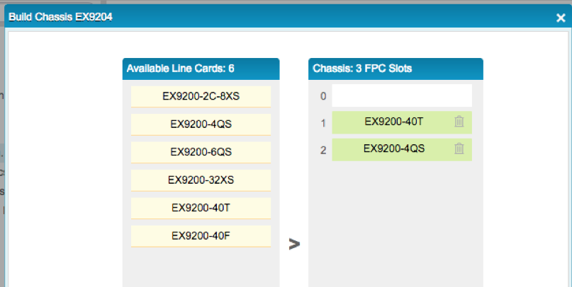
Figure 4. Build Chassis
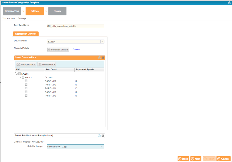
Figure 5. Create Fusion Configuration Template > Settings > Cascade Port Selection
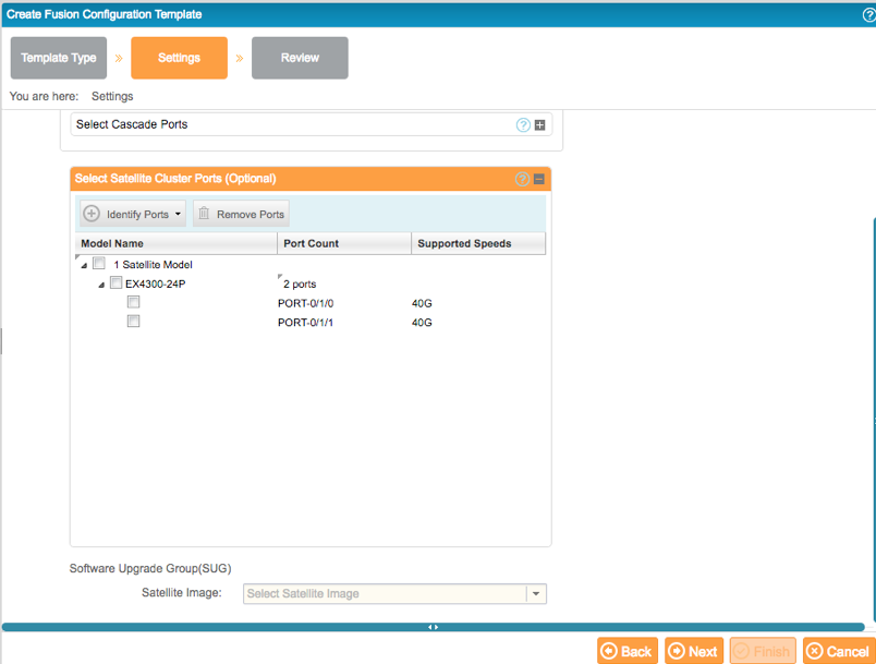
Figure 6. Create Fusion Configuration Template > Settings > Cluster Port Selection
Apply Junos Fusion Single Home with hybrid satellites Template
In order to apply a template, the user needs to select the template from the “Template Landing Page” and invoke the “Apply” button.
Network Director 3.0 supports two use cases in setting up Junos Fusion.
- Junos Fusion setup with devices running factory default configuration
- Junos Fusion setup by converting existing devices that are connected
The scope of this article is to illustrate setting up Junos Fusion with devices running factory default configuration. Converting existing devices is covered as part of another article.
Junos Fusion setup with devices running factory default configuration
This use case addresses the customers' need to bring up Junos Fusion with devices (aggregation and satellite devices) that are not managed by Network Director and the devices running factory default configuration. When the “Apply” action is invoked, the user is prompted to provide the DHCP Server and File Server details as the devices go through “Zero Touch Provisioning” once brought into the network. The only other information that the user needs to provide is the serial number or MAC address of the aggregation device. Network Director automates the rest of the configuration as devices get connected (according to the ports defined in the template) to the aggregation device. After the template assignment is successful, the details are displayed in the Junos Fusion Landing Page. No information about the satellite device is required; Network Director automates the solution as the satellite devices are connected to the configured cascade ports on the aggregation device.
In the apply template UI page, the default configuration that gets mapped in the DHCP/File Server is auto-generated by Network Director based on the template settings.
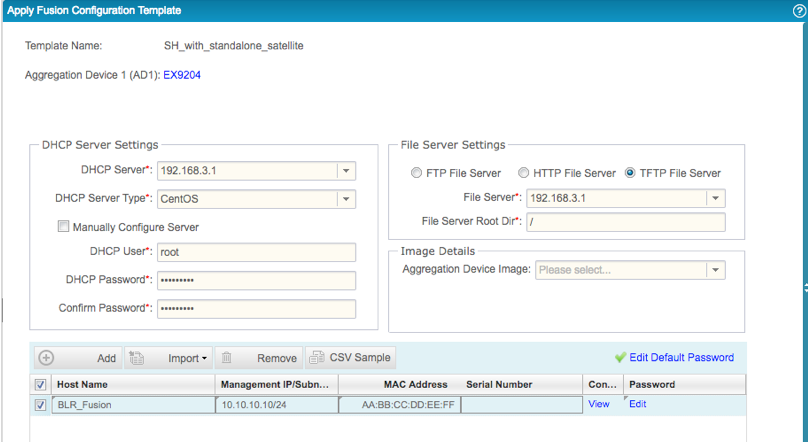
Figure 7. Apply Template (Unmanaged Devices)
Below is a quick overview of the various configuration elements related to Junos Fusion that is auto-generated by Network Director.
interfaces {
ge-1/0/0 {
cascade-port;
}
}
interfaces {
ge-1/0/2 {
cascade-port;
}
}
interfaces {
ge-1/0/4 {
cascade-port;
}
}
interfaces {
ge-1/0/6 {
cascade-port;
}
}
interfaces {
ge-1/0/8 {
cascade-port;
}
}
chassis {
satellite-management {
auto-satellite-conversion {
satellite all;
}
}
}
chassis {
satellite-management {
upgrade-groups {
default-sug {
satellite all;
}
}
}
}
As can be seen from the above configuration, the ports that are selected as "cascade-port" in the template will be configured as "cascade-port". If the port supports multiple speeds, Network Director would configure the port as "cascade-port" for the different speeds. Network Director also configures auto-satellite-conversion for all the satellite devices to enable plug-n-play. Lastly, Network Director configures a software upgrade group (default-sug) and maps all the satellite to this SUG. This is required for auto-conversion of switch to satellite when connected to the cascade port on the aggregation device.
Discovery/Management of the Aggregation Device in Network Director
After the template is applied to one or more aggregation devices, Network Director would have configured the DHCP server by mapping the management IP address to the device MAC address and staged the configuration file/Junos OS image to the file server. The required mapping of the file server to the DHCP options is also performed by Network Director. The next step is to bring the device into the network.
When the aggregation device with Junos factory default configuration is brought into the network, the device goes through Zero Touch Provisioning and retrieves the IP address from the DHCP server and the Network Director generated configuration from the file server. Network Director is notified about the device coming online (as Network Director is configured as a trap recipient) and the aggregation device gets discovered and auto-managed in Network Director. If the IP address of the discovered device is allocated for Junos Fusion aggregation device, Network Director checks whether there is a template assigned for the discovered aggregation device. If a template is found, Network Director gets the default SNOS image from the template and pushes the SNOS image to the discovered aggregation device. Network Director prepares the aggregation device by pushing the SNOS image. Network Director also executes the RPC to map the SNOS image to the SUG (default-sug) that is already configured in the device.
Once the device is discovered, it will be shown in tree view in Network Director as shown in Figure 8.
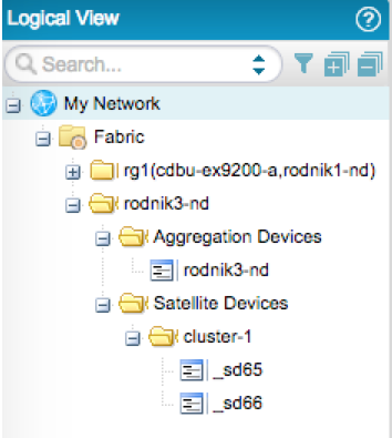
Figure 8. Junos Fusion (rodnik3-nd) Representation with Cluster (cluster-1) in Logical Tree View
Cabling Plan
A fully loaded Junos Fusion can have 128 satellite devices. For redundancy, each satellite could have one ore more connections to the aggregation device. It is not going to be easy to make all these connections without human errors. Therefore, Network Director generates a cabling plan report in PDF format that can be used to making the connections to the ports as defined in the template. We also saw that Network Director does not require any information about satellite devices. Network Director automates the configuration push as satellite devices are connected to the aggregation device. In order for the configuration push to be successful, the connection needs to match the ports selected in the template. The user can trigger the generation of the cabling plan from the “Manage Fusion Fabrics” landing page. Once generated, the cabling plan report can be downloaded from the "Reports" section.
 Figure 9. Generate Cabling Plan
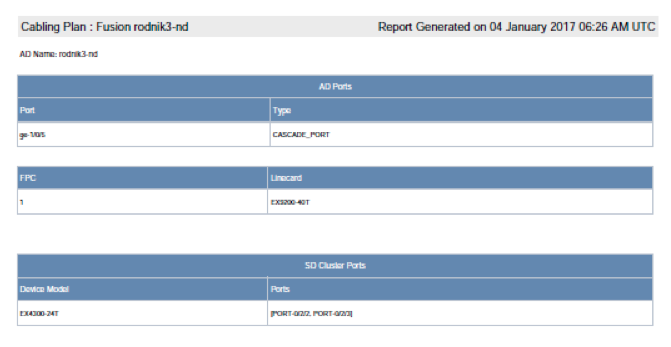
Figure 10. Sample Cabling Plan Generated by Network Director
Auto-conversion to Satellite Device from Standalone
The user follows the cabling plan and connects the satellite device running Junos OS or SNOS (in standalone mode) to one of the configured cascade ports (eg. ge-1/0/5) on the aggregation device. This in turn results in a link coming “UP” and notifies Network Director about the link event. Network Director executes a series of RPCs on the aggregation device to determine whether the configuration needs to be pushed for the connection made. If Network Director identifies that configuration needs to be pushed for a standalone device to satellite device, the following configurations are pushed to the aggregation device.
set chassis satellite-management fpc 65
set chassis satellite-management fpc 65 alias sd65
set chassis satellite-management fpc 65 cascade-ports ge-1/0/5
As can be seen from the above configuration, Network Director assigns FPC slot ID 65 to the connected device and the alias prefixed with “sd”. Network Director loops through the slot ID range and selects the first available slot ID for the connected device.
The prerequisites for platform auto-satellite conversion are the following:
- SUG created and the FPC slot mapped to one of the SUGs
- Auto satellite conversion enabled
- SNOS image availability in the aggregation device
- SNOS image mapped to the SUG
Network Director ensures that the connected device is able to join the Junos Fusion by automating all of the prerequisites to be met. Network Director automates prerequisites 1 and 2 by creating a default SUG and assigning all the satellites to the default SUG as part of the configuration staged for the aggregation device serial number or MAC address in the DHCP/file server. Network Director automates prerequisites 3 and 4 by pushing the SNOS image and mapping the SNOS image to the default SUG during discovery and management of the aggregation device. With all the above prerequisites met, the connected device will get auto converted from standalone mode to satellite mode. After the device joins as a satellite member in Junos Fusion, the aggregation device sends a syslog about the new satellite member coming online in Junos Fusion. Network Director/Junos Space Network Management Platform listens for this syslog and updates the physical and logical inventories based on the syslog.
Configuring logical interfaces/subinterfaces on extended ports
Unlike the default Junos configuration where a logical interface or subinterface (unit 0) is configured for all the ports, the extended ports by default are not configured with logical interface 0 (unit 0). As the logical interface or subinterface is not configured by default on all the extended ports, LLDP neighbors will not be able to list any connection on these ports. It is cumbersome to configure logical interfaces or subinterfaces for extended ports given the scale of a fully loaded Junos Fusion. Network Director simplifies this by auto-configuring a logical interface or subinterface (unit 0) on all the extended ports when the syslog about the new member joining the Junos Fusion is received. Below is the logical interface or subinterface configuration pushed to the aggregation device. Similarly, Network Director will automate the other satellite capable devices when connected to cascade ports on the aggregation device to get auto-converted to satellite members and join Junos Fusion. If multiple satellites join the Junos Fusion within a stipulated duration (say, 2 minutes), Network Director would configure a logical interface or subinterface on the extended ports for all the FPC slots as a single job.
set interfaces ge-65/0/0 unit 0 family ethernet-switching
set interfaces ge-65/0/1 unit 0 family ethernet-switching
After the logical interface configuration is pushed to the extended ports, Network Director triggers a topology discovery automatically which in turn would show all the connected devices to these extended ports through LLDP.
Auto-conversion from Standalone Satellite to Satellite Cluster
The configuration for a cluster is more complex and error prone when compared to the configuration for standalone satellites. For a cluster to be formed successfully, every member in the cluster need to be configured with its MAC address. Any error in the configuration will result in the connected device not being able to join the cluster. Network Director removes all these complexities from the user by generating and provisioning the cluster-related configuration as devices are connected.
In the previous section, when a satellite device comes online, Network Director pushed the logical interface configuration to all the extended ports for the satellite device FPC. If there is any connection on the cluster port, Network Director would automatically know about the connection through LLDP and execute a series of RPCs on the aggregation device to determine whether cluster configuration needs to be pushed to the aggregation device. Alternatively, when the user connects the cluster port (extended port) on a standalone satellite device (for example, FPC 65) running SNOS that is part of Junos Fusion to that of the cluster port on another standalone switch running Junos OS or SNOS, Network Director gets notified about the link coming up online. The cluster port on the standalone satellite device is an extended port on the aggregation device; therefore, the connection with the cluster port on another standalone switch is notified to Network Director. Network Director executes a series of RPC commands on the aggregation device and correlates the information from these RPC commands to determine whether the standalone satellite device and the standalone switch connected through the cluster port need to be converted to a satellite cluster. Network Director would only do that if the template used to bring up the Junos Fusion has cluster ports configured and the connection matches the cluster port in the template. If the above conditions are met, Network Director would generate and push the CLIs to convert the standalone satellite device to a cluster and also generate the CLIs to add the standalone satellite switch to be part of the cluster.
As can be seen from the above generated CLIs, Network Director deletes the standalone satellite (65) and adds it as part of the cluster (cluster-1) and also adds the standalone switch (66) to the cluster (cluster-1). Network Director also pushes the configuration to remove the FPCs (65 and 66) that are part of the cluster (cluster-1) from any other SUG if they are present. Network Director completely automates all of the tasks that are required for cluster formation as devices are connected to the aggregation device. If there are redundant connections from the standalone satellite (65) to the aggregation device, all the connections would be added as cascade ports to the cluster (cluster-1) configuration.
After pushing the standalone to cluster configuration on the aggregation device, Junos platform triggers the conversion of the satellite device to a cluster member and once the device joins Junos Fusion as a cluster member, Network Director is notified via a syslog from the device about the cluster member coming online. Network Director checks whether a logical interface or subinterface (unit 0) needs to be configured for any of the extended ports for the new cluster member. if required, Network Director configures a logical or subinterface (unit 0) for the extended ports and automatically triggers a topology refresh which will then start showing the immediate neigbors that are connected on these extended ports. Network Director would then check whether any of the neighbors connected to these extended ports are connected to the cluster port and if so would add the neighbor to the existing cluster. This process is repeated until the entire ring of cluster devices are discovered and added to the cluster configuration. Thus Network Director automates the discovery and configuration of the entire cluster without human intervention.
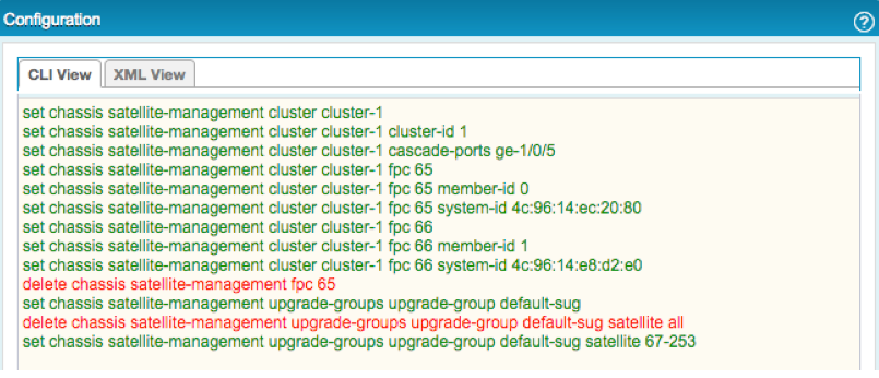
Figure 11. Sample Standalone-to-Cluster Conversion Configuration
Managing Single-Home Junos Fusion
After the Junos Fusion is set, it may be required to upsize or downsize the scale of Junos Fusion by adding or deleting a cascade port. Network Director eliminates the complexity of these operations from the user by automating several of the subtasks and ensures that these operations are successfully executed on the aggregation device. Once the Junos Fusion is discovered and managed in Network Director, it would be listed in the “Manage Fusion Fabrics” landing page.

Figure 12. Manage Fusion Fabrics Landing Page
The user needs to select the Junos Fusion instance from the landing page and invoke the “Edit” action to start making changes. The user can add or remove cascade ports to make changes to the configuration. Alternatively, the user can also “Remove” standalone satellite devices by switching to the “Satellite Devices” tab. In case of a cluster (which is connected as a ring), a single satellite device removal would result in breaking the ring topology; hence, the operation to remove a satellite device from a cluster is not supported. The user can however remove the entire cluster, which would result in updating the configuration and also shutting down the devices so that they do not carry any traffic.

Figure 13. Edit Fusion Fabric > Satellite Devices Tab
As can be seen from the below CLI configuration generated and pushed to the aggregation device, Network Director enables the cascade-port knob on the selected port, which is to be provisioned as a cascade port. If the selected port is configured with logical interface “0”, Network Director would take care of deleting the logical interface “0” from the port configuration (as cascade-port and logical interface “0” are mutually exclusive). Similarly, when a port is removed from the workflow, Network Director would delete the “cacade-port” configuration on the selected port.
set interfaces ge-1/0/0 cascade-port
Summary
This article illustrates how Network Director automates the deployment of single-home Junos Fusion with hybrid (standalone and cluster) satellites by automating various aspects that are required in deploying the Junos Fusion. In summary, Network Director:
• Helps the user create a template and apply the template to bring up one or many instances of Junos Fusion
• Preprovisions the device for Zero Touch Provisioning
• Provides a cabling plan to the user to make the connections between the aggregation and satellite devices
• Automates the satellite device configuration by pushing the configuration as satellite capable devices are connected to the configured cascade ports on the aggregation device
• Automates the cluster solution as devices are connected
• Helps to troubleshoot and fix connection errors by running a connectivity report to diagnose problems
• Helps in managing Junos Fusion post deployment