Introduction
The Internet Service Providers (ISP), in addition to basic IP connectivity services, offers their customers value added services [typically for added cost]. One such VAS is the inspection of traffic payload before it reaches the end customer LAN, or more precisely to before it reaches the customer systems (host) network.
The services granted by the ISP may include simple monitoring and analytics, content enrichment, security threat monitoring or possibly active DDoS scrubbing.
Figure 1 traffic inspection service
There are multiple locations in the network where traffic payload inspection can be performed. However, due to operational and business considerations it is common to leverage a centralized approach where the service granting device(s) are located across very few data center sites, as seen in Figure 2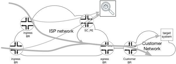
Figure 2 Centralized inspection service for selected traffic.
The following write-up provides a high level solution specification of one such method for performing the services described above; selection, re-direction and re-insertion of traffic in a typical ISP network.
Goals and non-Goals
This High Level Solution Specification has following goals:
- It is applicable to unidirectional traffic flow toward “target system” only. This is not a solution when full session-aware [bi-directional] service is needed.
- It provides a solution to re-direct target IP traffic for services irrespective of source IP or point of entry into the ISP network.
- In the case of Dual Homing destination systems, the proposed solution:
- Provides redundancy in the case of, customer Internet Border Router (C_BR), egress Internet Border Router (e_BR) or inter-AS link failure.
- Selects an e_BR that is closest (IGP based) to the service delivery cluster or load-balance among all e_BR.
- Redirecting only selectively targeted traffic, explicitly specified by customer over OOB [Out Of Band] (WEB-API, Portal), to the services delivery cluster. The redirection could be either IP host address or IP prefix based, and must be more specific/accurate from the prefix advertised by peer_BR through eBGP.
- It is assumed that the redirection request is asynchronously triggered, on-demand by customer, the timing is out of scope for this write-up solution.
Assumptions
The principal architecture of an ISP network follows below guidelines:
- MPLS network is implemented as type A, defined as follow:
- Utilizing LDP, RSVP or mix of both for LSP signaling protocols.
- LSP are signaled toward the loopback addresses of BR’s, to form full mesh topology.
- Only the primarily loopback [for each BR] address is used for MPLS FEC designation for all participating IEs.
- BR’s will set BGP NH to self, when re-advertise prefixes into iBGP, to allow the use of LSP for data forwarding.
- IGP protocol utilizes OSPF or ISIS (or mix of both):
- Signals the IP addresses of all BR’s loopbacks.
- May signal internal links addresses.
- Does not carry any customer addresses nor addresses of inter-AS links.
- BGP runs on BR only.
- BR may be a core/transit router for other BR’s (P/PE)
- If router is not BR, it does not run BGP.
- BR’s will set BGP NH to self, when re-advertise prefixes into iBGP, to allow the use of LSP for data forwarding.
- Although the solution leverages MPLS, no assumptions are made nor is there a dependency on L3VPN.
- The Customer network BR (C_BR) utilized eBGP for IPv4 and IPv6 address families advertisement. Sessions are established with ISP’s BR utilizing the IP addresses of inter-AS links.
- Servicing Cluster
- Is L3 device/Cluster of devices. Connectivity is based on an IPv4/IPv6 address/es.
- Supports static routing and BGP routing but only for plane IPv4 and IPv6 (AFI=1, SAFI=1 and AFI=1, SAFI=6 ) at most.
- Supports two separate egress/ingress path’s – one used to receive traffic “to-service” and other used to send traffic out applying the service. For the purpose of this document we would referenced as on_ramp and off_ramp respectively.
The Architecture
Figure 3 below graphically represents a network outlining four types of BR nodes that perform different function in solution architecture. Below is a breakdown of each component highlighted in the below network architecture.
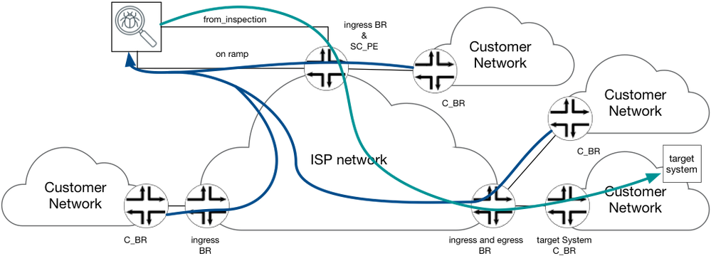
Figure 3 reference network architecture
Customer Border Router (C_BR)
Customer BR is a IPv4 and/or IPv6 capable router, belongs to customer Network. C_BR peers with i_BR using standard BGP or use static routing to forward traffic to ISP network.
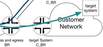
Target System C_BR is C_BR that connects customer network hosting target system host to ISP network.
Ingress Border Router (i_BR)
Every Border Router in ISP network could potentially be an i_BR (as well as e_BR). An i_BR is defined in context of given “target system” and flows toward it. The i_BR is a BR that receives traffic toward given “target system” in one of customer’s networks from other customer network.

Therefore, the i_BR is responsible for:
- Selecting IP Traffic designated to “target systems” out of all traffic received on any/all interfaces
- Forwarding the traffic designated to “target systems” to (redirect) the respective Services Cluster (via Service Cluster PE)
Services Cluster PE (SC_PE)
This router is the network gateway to the services cluster, it bridges both ingress services and egress services interfaces – on_ramp and off_ramp. SC_PE need to maintain the forwarding states such that traffic received from i_BR, delivered to the Services Cluster via on_ramp interface, will not be redirected back [in a loop] to the same interface (on_ramp), as it egresses through the off_ramp interfaces but forwarded toward target system.
Egress BR (e_BR)
Every BR in ISP network could potentially be an e_BR (as well as i_BR), it connects C_BR of customer network hosting the Target System [Host]. An e_BR is defined in context of given “target system” and flows toward it. The e_BR receives IP Packets addressed to “target system” from the other network nodes in ISP network and forwards it out toward C_BR and the Target System.

Clearly in production networks a given edge router may simultaneously serve as both ingress and egress BR. It may also serve as the Service Cluster PE, all in one. Therefore, the proposed solution must ensure that all of the above functionality and “Router – Personality” may be served by a single router.
Also take note, at seen in Figure 8, at a given moment traffic destined to multiple target system could be serviced. Therefore, inter–AS link could be viewed as both ingress BR to one Network and egress BR to another Target network.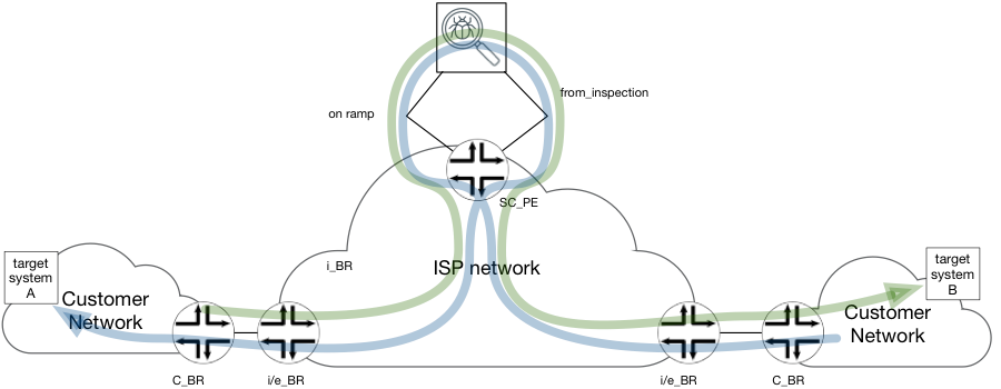
Figure 8 Multiple "target systems"
Traffic selection technique
There are two types of IP Traffic selection techniques discussed: filter based and forwarding based.
The filter-based approach
A selection base of filter (aka ACL) enables more flexible rules. The selection criteria is based on Internet 5-tupple, CoS bits, L4 flags, etc. there should be no dependency between destination prefix length and the routing information. In principle, filter based selection will install a filter/ACL on the data path and specify forwarding next-hop AS.. The filter instantiation could be done via the management plane (NetConf/YANG, CLI, OpenFlow, etc.) or via control-plane protocol (BGP Flow-Spec).
Alternatively should the enforcement/selection be made to be inclusive [default (global) context], IP traffic received on any interface that matches the filter (i.e, destination IP is the target system network AND protocol port is SMTP) would be redirected and designated to the Services Cluster.ƒP
None withstanding, creating multiple contexts and attaching filters to the inter-AS interfaces [one or many], allows limiting redirection to traffic that was received on specific inter-AS interfaces.
Filter based selection in combination of source IP, L4 protocol or other L4 information, creates a more refined and granular redirection action or discard, rate-limit and re-classify of the designated IP traffic.
At same time this method inherently consumes much more resources form routers data-path and harder to manage. Therefore, use of this method is not optimal when “target system” is simply identified by destination IP address. The routers have specialized function to look up and match on destination IP address – the forwarding table.
Forwarding base selection
In principle, forwarding based redirection will insure and leverage a more specific forwarding state in all i_BR’s FIB (route with longest prefix) in contract with normal route propagation and advertisement of the target system C_BR.
The target system C_BR advertises reachability to a set of networks as set of prefixes it directly connects to, due to its location in the network one of the advertised prefixes will covers the target system address. Filter based Forwarding on the other-hand could be done via the management channel (static route, OpenFlow, etc.), or via the control-plane protocols. If forwarding action taken into the default (global) FIB, IP traffic received on any interface that matches the inserted route (i.e, the destinations is target system) would be re-designated and sent to Services Cluster . Forwarding based selection and redirection applies more constrains on the selection rules.
Utilizing multiple FIB contexts and assignment to one or many inter-AS interfaces, allows limiting the redirection of traffic to that received on a limited specific set of inter-AS interface.
Forwarding based selection prohibits the use of source IP, L4 protocol or other L4 information as selection criteria. In Addition, it limits the granularity of action taken to only: redirection or discard of selected traffic. Rate-limiting, shaping, QoS re-classification are not commonly available options across router vendors and products.
The main benefit of this method are:
- Ability to use basic management and/or simple control-protocols to insert a route (e.g. Static, ISIS)
- High scalability 100,000’s (modern high-end routers supports large FIB holding a few million routes)
- Little if any performance impact at scale – routers are designed to perform LPM [Longest Prefix Match] lookup efficiently.
For this Solution Architecture specification, the Forwarding-based selection is recommended, the main criteria’s to making this decision are:
- Traffic selection based on destination address only.
- No performance degradation at scale.
- No need for specialized protocol to install re-direction action.
As per assumptions made above [Assumptions] the Services Cluster is capable of exchanging BGP, thus it is used to insert the address (oust or prefix) of “target system”. It is assumed that Service Cluster is provided with the target address through a OOB management interface.
Figure 9 Redirection routing of target systems addresses
The Services Cluster, will not participate in IGP, as such the following is assumed:
- eBGP session between Service Cluster and SC_PE will be established using “to_inspaction” interface addresses
- Service Cluster is using the private ASN; all prefixes announced by the Service Cluster are marked by “no-export” community. In addition, marking will be done through a custom community which identify the path as coming from (particular) Service Cluster, is recommended.
- SC_PE will mark NLRI [Network Layer Reachability Information] learned from the Services Cluster with high-value Local Preference attribute and re-advertise through iBGP cloud with BGP NH set to “self”.
Setting BGP NH to “Self”, enables traffic re-directed to the Service Cluster utilizing a MPLS LSP (LDP or RSVP signaled) to allow the crossing of the ISP backbone.
High Value Local Preference attribute, is needed only when the prefix length of the “target system” advertised by the Service Cluster and prefix length advertised by C_BR are equal in size. In this case LocPref secures that path from the Service Cluster is preferred and traffic will be redirected as expected to the Service Cluster.
Service Cluster IP Traffic Processing – Ingress
The on_ramp interface of the Service Cluster is the ingress interface where it expects “pre-processed” IP traffic. The Service Cluster signals eBGP over this interface with the SC_PE router, and advertises to the SC_PE the “target system” addresses/prefixes. This NLRI carries “no-export” well-known community. It is assumed that the Services Cluster ASN is using a private space. If multiple Services Clusters exist on the ISP network [at different location], they must each use the same ASN, as there is we assume no need for connectivity between two or more Services Clusters.
The SC_PE router stores the prefixes learned from the Services Cluster into the default IP RIB and FIB (inet.0, inet6.0) and then re-advertises it to iBGP of ISP network with “no-export” well-known community.
SC_PE router will not accept any NLRI from any ISP iBGP, as this information is not needed by the SC_PE router, and using filtering will result in the reduction of resource utilization on SC_PE router [as highlighted above The filter-based approach].
SC_PE router will not advertise any NLRI to the Service Cluster, as this ingress interface/s is not expected to be used to send IP traffic out [only ingress] .
Traffic redirection on ingress BR
All IEs (ingress BR) in ISP network will receives update originated from Services Cluster. This path represents the best path for the “target system” [either due to LSM or high LocPref attribute], therefore route will be installed in all BR default instance FIB (Inet.0/inet6.0). BGP NH is set to SC_PE loopback address, the MPLS LSP will be used for forwarding traffic to the Services Cluster on top of the ISP network. Finally the SC_PE router, will perform IP lookup and BGP route from the Services Cluster will assure traffic is forwarded to the on_ramp interface at the Services Cluster.
For special cases, where the iIE and SC_PE are the same device, updates from the Services Cluster will create a FIB entry and therefore traffic designated to Service Cluster [i.e. destined to the “Target System”], will be forwarded base on basic IP lookup and immediately pushed out to the on_ramp interface.
The above solution fulfill the requirements to provide a fully dynamic reachability matrix, while minimizing the routing configuration complexity on both – SC_PE and the Services Cluster.
Service Cluster IP Traffic Processing – Egress
The off_ramp[1] interface of the Services Cluster will uniquely be identified as the only egress interface, as such it must maintain reachability to all possible designated “Target Systems”. For most cases, Default Router would suffice, however the use of static default route is not optimal and not recommended from a reliability perspective. Instead, eBGP should be leveraged between the Services Cluster and and SC_PE router. The SC_PE routers will advertising 0/0 route with “no-advertise” community.
On SC_PE router, traffic received on off_ramp interface should not be forwarded using the default FIB (inet.0), because it holds the route to “target system” advertised through BGP by Services Clustrer itself pointing to the on_ramp interface. To avoid route loops, a “off_ramp_vr” virtual-router (VR) instance will be created on SC_PE. This VR peers with the Services Cluster using eBGP through the off_ramp interface addresses. SC_PE will not accept any NLRI from the Services Cluster signaling exchange, and will only advertise the above mentioned default route. See Figure 10 Routing on off_ramp interface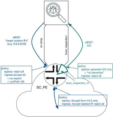
Figure 10 Routing on off_ramp interface
Routing toward target system from SC_PE toward C_BR
The IP Traffic egressing the Service Cluster [ “off_ramp_vr” FIB] will be populated with labeled routes advertised by the egress IEs, see below the details:
Egress BR routing
- For customer networks that maintain eBGP session with ISP:
- The egress BR peers with the Customer BR using eBGP session (AFI=1 and AFI=2). The NLRI learned over this session are stored in default IP RIB (inet.0/inet6.0)[2]
- Additionally, for Customers w/ Target Systest/s identified to use the Services Cluster, the all NLRI learned from this customer’s C_BR are stored in the labeled IP RIB (inet.3, inet6.3).
- For customer networks that do not maintain eBGP session with ISP:
- The static routing is used on e_BR. The static routes are stored in default IP RIB (inet.0/inet6.0).
- Additionally, for Customers w/ Target Systest/s identified to use the Services Cluster, the static routes are stored in the labeled IP RIB (inet.3, inet6.3).
- Prefixes form labeled IP RIB are advertised into iBGP with BGP NH set to “self” (loopback of egress BR). This advertisement assigns non-restricted label to customer prefixes, the value of this label is unique per C_BR’s inter-AS interface.

Figure 11 routing from egress BR toward customer network
Please note that number of routes in the labeled RIB depends on a particular ISP situation – customer profiles, business offering, type of services delivered through the Services Cluster, etc. On one extreme the number of routes could be as big as the plain IP RIB, on average though it should be kept to only a few prefixes.
The egress BR should not accept any labeled NLRI, using the import policy on iBGP session.
Egress BR forwarding
MPLS FIB entry is signaled on the egress BR, for a given label pop and forward operation for traffic egress the interface to C_BR. IP packet received with the label advertised by iBGP as above, are forwarded to C_BR without IP lookup on e-BR.
See Figure 12 MPLS forwarding of traffic to target system on egress BR
Bypassing IP lookup at e-BR allows a single router to hold both ingress and egress BR roles simultaneously and connected to the same “target system”.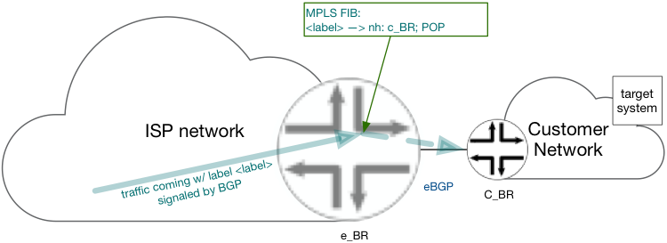
Figure 12 MPLS forwarding of traffic to target system on egress BR
iBGP infrastructure for labeled BGP routes
There are 3 architectural options for delivery labeled BGP routes from e_BR to SC_PE:
- Over direct iBGP session from all eIE to SC_PE. This is the preferred option when a combination of the below:
- The number of SC_PE in network is very small, in range of 2-3
- SC_PE are dedicated devices, that do not act as IEs
- Number of eIE is relatively low (~50-100), making it practical to maintain the number of sessions on SC_PE
- Using a Route Reflector [RR] shared with well-planned IP routing scheme. This option would be preferred if number of labeled NLRI is relatively low and/or total number of labeled and plain IP NLRI is manageable by the RR.
- Using dedicated RR infrastructure for labeled NLRI, if scaling requirements exceed the above mentioned parameters .
Please note that the use of BGP ADD_PATH may result in significant increase in the scaling requirements. In such case dedicated RR infrastructure may be required.
This Solution specification design holds no specific preference towards one solution over another, rather leaves the decision at the hand of the network designer and or operator.
Labeled IP routing at the SC_PE
The iBGP labeled routes received at the SC_PE are inserted into “off_ramp_vr” IP RIB (VR.inet.0, VR.inet6.0) and respective FIB. The learned labeled NLRI carries the; customer prefix, label assigned by e_BR [unique for C_BR], and BGP NH equal to the originating e_BR’s loopback.
The BGP NH will be stored on the default labeled RIB (inet.3, inet6.3), the same location where LDP and RSVP routing will be is stored. As a result, the “off_ramp_vr” IP RIB, now holds the IP prefix associated with a dual-push MPLS operation; inner label to originating form a labeled NLRI and outer label originating from the NH resolution in the default labeled RIB.
The SC_PE will not advertise any labeled NLRI, rather rely on the export policy on iBGP.
Egress Forwarding on SC_PE router toward e_BR
IP packet received through off_ramp interface, will go through IP lookup in “off_ramp_vr”. Final forwarding decision will apply two MPLS label encapsulation, and then send the IP traffic through the core facing interface.
The outer label carries the traffic over LDP/RSVP LSP to the egress BR. Provided that core MPLS is configured to perform PHP, egress BR will accept the IP Traffic encapsulated with only a single label – inner one. As described earlier in this document, e_BR pops the final label and forwards the IP Traffic to C_BR.
Scaling and resiliency consideration
Border Router and SC_PE routers
The network architecture between given ISP to the other connected autonomous systems could be classified as client, peering or transit.
- eBGP routing exchanges prefixes reachability between ISP and all 3 types on connected networks
- Peering, Transit, Customer Networks
- Typically prefixes learned through a transit provider will hold the majority of all prefixes in an ISP routing system.
- Please note that services rendered by the Services Cluster requiring redirection, will be provided to ISP customers and not transit or peering partners.
- As a result, the number of prefixes advertised by C_BR’s and installed in the labeled IP RIB is significantly smaller then number of all prefixes in the basic IP RIB and FIB (where prefixes representing both the customers as well as from transit providers and peering are required).
At time of writing, the Internet routing table hold ~650k IPv4 prefixes and ~30k IPv6 prefixes. Rough assumptions place the need for a IP RIB and FIB (inet.0, inet6.0) that is capable of holding ~680k prefixes learned from external peers, in addition to a few selected hosts/prefixes representing “target systems”. Roughly ~700k prefixes.
Prefixes learned from the C_BR are also held in the labeled RIBs, the maximum size of labeled RIB could be conservatively estimated to be much lower than ~630k prefixes (IPv4 + IPv6). Reasoning: a given e_BR will hold in the RIBs (inet.3, inet6.3) only prefixes learned from the directly connected customers C_BR, but not from the peering and transit peers.
Labeled prefixes learned by the SC_PE from the e_BR are hosted in the labeled RIB and FIB of “off_ramp_vr”. The maximum size of labeled RIB and FIB could be estimated to be lower than ~630k prefixes (IPv4 + IPv6) because not all customers are subscribed to the Services Cluster and services will not be rendered to transit providers and peering partners.
Please note that the SC_PE will not be required to host all prefixes in the default IP RIB and FIB. It should only hold prefixes learned from the Services Cluster “target system” addresses.
Table below summarize the RIB and FIB size (where X is full table size – 630k for Internet as of day of writing)
Table 1 Scaling considerations
|
Router Role
|
Inet.0 + inet6.0
(RIB & FIB)
|
Inet.3 + inet6.3
(RIB only)
|
Off_ramp_vr.inet.0
(RIB & FIB)
|
|
SC_PE
|
“target systems” prefix #
|
0
|
< X
(customer’s prefixes)
|
|
E_BR
|
X + “target systems” prefix #
|
< X
(customer’s prefixes)
|
0
|
|
Dual-role (SC_PE and e_BR; see below)
|
X + “target systems” prefix #
|
0
|
< X
(customer’s prefixes)
|
Please note that combined, dual-role device would need to handle a FIB size up to twice the number of prefixes.
Service Cluster Scale and Resiliency
Services cluster scaling and resiliency utilize a common architecture of deployment; all-active N+1 model. The Service cluster in a given zone/network area is composed of multiple (N) instances of services nodes. For VNF deployment use cases, this is the common deployment architecture. All forwarding between network (SC_PE) and multiple service nodes of given Service Cluster will be based on IP routing, as such the architecture inherently may leverage ECMP of SC_PE platform. It is worth noting that capabilities like wide ECMP (up to 64 paths), ALB (adaptive load balancing) as well as symmetrical and consistent hashing, made available on MX and PTX[3], could significantly improve the overall solution and reduce the cost associated with the architecture resiliency and scale by removing the requirements for a dedicated load balancer in Service Cluster.
The ALB function monitors load/traffic and utilizes ECMP to adjust LB hash-to-NH mapping leveling the traffic distributed to each member. This helps reduce the mice-and-elephant flow impact on hash-based load-balancing.
The consistent symmetrical hashing ensures that the same ECMP path are used for forwarding packet of a given bi-direction flow. In case of a failure of subset of ECMP paths, flows carried by these paths are re-distributed to the remaining established paths, though flows already anchored to non-affected path are not re-distributed. This prevents unnecessary session distribution to non-affected service node.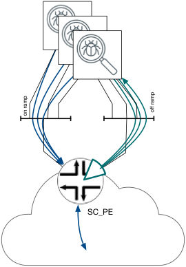
When a single Service Cluster is connected by two SC_PE, for redundancy purposes, two iBGP path for each “target System” IP [one for each of SC_PE] are learned by i_BR, so it would select one of them base on standard BGP algorithm while keeping the other path as backup. Should the i_BR be enabled with BGP PIC edge, a typical failure would allow for sub-second switchover should of one of SC_PE fail.
Service Cluster Geo-redundancy and Geo-scale-out
For single network, multiple Service Clusters are expected. These may be configured in a way that improves redundancy and scale. Provided that a given “target System” is served by multiple Service Clusters [for reasons of scale and redundancy] the SC_PE at different locations would advertise through iBGP a IP address/subnet of “target system”. The i_BR may now select one of few Services Cluster base on IGP proximity (or other/different attributes). The Geographic Redundancy nature achived through the above mentioned architecture maintains a clean distribution of load across multiple Service Clusters in different locations, in addition to reducing overall latency and provides alternative (2nd best) Service Cluster, in the case of selected primary failure .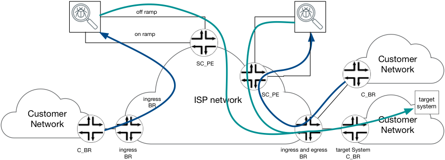
Figure 14 Service Cluster Geo-redundancy and Geo-scale-out.
This architecture enables the scaling of service not only by upgrading Service Clusters at existing locations, but also by instantiating new Service Cluster locations when needed.
Finally, should a given Service Cluster run out of capacity, other Service Clusters maintaining enough resources are relatively easy to utilize and re-distribute the load. This would be achieved though removing some of the “target system” IP from an existing BGP advertisement.
SC_PE and BR using the same router
Egress routing
The solution described above [Forwarding base selection] opens the opportunity for single router to hold both roles: SC_PE and BR simultaneously. There are two clearly marked options for combing both roles:
- Using labelled IP RIB and “off_ramp_vr” simultaneously.
- This would require additional configuration or routing policy and inter-RIB prefix leaking. It is also less scalable as some routes would need to be stored 3 times. The benefit of this solution is; easy migration from BR to dual-role.
- Leveraging “off_ramp_vr”. The labeled IP routes are imported in a same way described in the SC_PE configuration and exported as labeled IP RIB (inet3, inet6.3) e_BR configuration.
Provided that the migration from BR to dual-role is not common, option B offers better scaling and a simpler configuration without significant limitations.
Dual-role router, peers with Customer BR by signaling an eBGP session (AFI=1 and AFI=2). The NLRI learned over this session are hosted on the default IP RIB (inet.0/inet6.0). Targeted Systems, designated to leverage the Services Cluster, their NLRI will be hosted in the “off_ramp_vr” IP RIB (off_ramp_vr.inet.0, off_ramp_vr.inet6.0). The prefixes form “off_ramp_vr” will be advertised through iBGP with BGP NH set to “self” (loopback of router). This advertisement allocates non-restricted label to customer prefixes. The value of this label will be unique per C_BR’s inter-AS interface.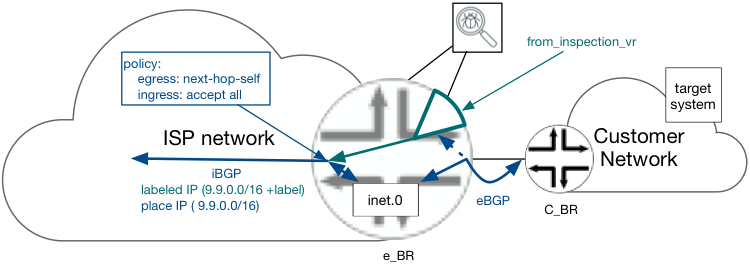
Figure 15 Egress BR and SC_PE coexistence
Please note that the number of routes in “off_ramp_vr” are the sum of prefixes learned from all e_BRs in the network, plus the locally connected customers (designated for the Services Cluster) and depends on particular ISP scenario – customer profiles, business offering, type of inspection services.
The router accepts labeled NLRI advertised be e_BR.
Egress forwarding
The MPLS FIB and IP entry on a duel-role router will work as follows:
IP forwarding entries are instantiated in the default and “off_ramp_vr” context. Traffic from the local Services device could be delivered to locally connected customers, as well as to customers behind remote e_BR (over LSP).
Additionally, MPLS forwarding entries will be hosted in the default context (mpls.0). These entries assign for a given label pop operation and forward action out of interface to C_BR. IP Packets received w/ label advertised by iBGP as above, are forwarded to C_BR without IP lookup at e-BR. This allow delivery packets form remote Service Cluster to locally connected customers.
Bypassing IP lookup at e-BR allows single router to perform as both ingress and egress BR simultaneously and for the same “target system”.
Platform selection
The proposed solution architecture is fully compliant with the Juniper MX and PTX network devices. Obviously for this devices FIB as well as the installed licenses need to be considered:
- The MX w/ ”-R” license and latest RE offers the highest scalability.
- PTX offers reasonable scaling with high bandwidth density.
As solution described here is based on open standard, other products may be compliant as well, and to a degree dictated by particular product characteristics. However, for Juniper portfolio, MX and PTX product families are the one designed and developed to act as Internet Border Router and ASBRs nodes.
Security considerations
The proposed solution does not consider changes to the control plane or data plane between the ISP network and customer’s, peering partner and transit providers networks. There is no change in data plane processing of packets incoming from above networks. Therefore network security is not impacted by this solution, and is as good as in network of similar design but without centralized traffic inspection.
Obviously OOB/Web-based interface use to provide “target system” IP address(es) could be compromised and in result force redirection of extra traffic. This could result in overloading Service Cluster or black hole of this traffic in “off_ramp_vr”. Securing OOB/Web interface is out of scope of this document. Risk of black hole could be removed by:
- Installing default route in “off_ramp.vr” context that points to default FIB, and
- Allow importing all iBGP routes into SC_PE default IP RIB and FIB.
Above modification would increase RIB and FIB capacity requirements on SC_PE.
Solution variations
Service Cluster supporting BGP-LU
If the Services Cluster supports BGP-LU, and can use labeled IPv4 and IPv6 routes for forwarding purposes, the configuration of SC_PE can be significantly simplified by removing “off_ramp_vr” instance. In this case SC_PE would act as simple BGP-LU BR in default context.
An Example of a Services Cluster that support BGP-LU is Juniper SRX family of firewalls.
All i_BR support BGP-LU
If all i_BR devices support BGP-LU (not only the e_BR), the “target system” addresses advertised by SC_PE could be of labeled IPv4/IPv6 NLRI. This would enable MPLS forwarding all the way from ingress BR down to Services Cluster. This opens additional possibility of overwriting shortest-path routing in the core in addition to better distribute Services workload among all available Services Cluster’s.
Services Cluster do not support BGP
Routing on on_ramp interface.
As all BR’s need to learn the “target systems” IP via iBGP, this addresses need to be generated somehow. This could be accomplished in two ways:
- From SC_PE. The SC_PE need to be provisioned with static routes to all active “target systems” as specified on OOB/Web interface. Then this routes are advertised into iBGP as plain_IP routes or labeled routers.
In later case i_BR are expected to support BGP-LU, but as benefit, no IP lookup is needed on SC_PE on on ramp direction. The NetConf/YANG interface could be used between OOB/WEB portal and SC_PE to insert/remove “target system” addresses as it appears on OOB/Web interface.
- From RR/Route Server/BGP SDN controller. In such case “Target system” IP addresses/prefixes are inserted into iBGP with crafted BGP next-hop set to IP address of SC_PE. The SC_PE should be provisioned with default static route in their default IP FIB (inet.0, inet6.0) pointing to on_ramp interface IP of Service Cluster. The SC_PE may not accept any iBGP route. The BGP controllers offers typically more advanced APIs to insert/remove prefixes to/from BGP.
The selection between above option depends on OOB/Web portal software infrastructure, and ISP capabilities of use API, and is out of scope of this document.
Routing on off_ramp interface
The Services Cluster need to be provisioned with either default route or all “target system” IP routes by OOB/Management interface. This is out-of-scope of this document. It is recommended to enable LFM or CFM or other type of keep-a-live between L3 off_ramp interfaces on SC_PE and Service Cluster, depending on common capabilities.
Services Cluster is transparent at Layer 3.
Some Services Clusters may appear as L2 switching devices, while still capable of applying a service at higher stack levels. This type of Services Cluster might not participate in IP routing (BGP), and will likely require slightly different configuration of SC_PE. See Figure 16 to/off_ramp routing for L2-only Service Cluster
Figure 16 to/off_ramp routing for L2-only Service Cluster
The iBGP session is formed over to/off_ramp interfaces between default routing instance and ”off_ramp_VR” using interface addresses. The ”off_ramp_VR” is configured as RR for this session and is provisioned with static routes representing “target systems” as provided by OOB.
This static routes has to be:
- Configured with no-install knob to be kept out of “off_ramp_vr” FIB. This way traffic arriving on SC_PE’s off_ramp interface is forwarded based on less specific labelled route.
- Configured with protocol priority higher (worst) then BGP-LU – learned prefixes. This way if prefix of “target system” as defined via OOB and learned from e_BR over BGP-LU are equal, the one form BGP-LU is best and active, so is installed in FIB.
In addition to static routing, export iBGP policy that allows advertisement of “target system” prefixes only and mark them with “no-export” community and change BGP next-hop to self.
This requires integration between SC_PE and OOB/Web API portal for managing configuration changes - adding/removes static routes and policies. The NetConf seems to be best option available at time of writing. This is perfect use case for use of Netconf/Yang and JUNOS ephemeral configuration when supported by JUNOS software release.
[1] This interface is named also off_ramp by some Service Cluster device/software vendors
[2] For customers who’s C_BR do not have BGP session with e_BR, static routing is used. The static routes are stored in default IP RIB (inet.0/inet6.0)
[3] Symmetrical hashing only at time of writing.
AttachmentsConfiguration Example - Light-weighted redirection and reinsertion.pdf